


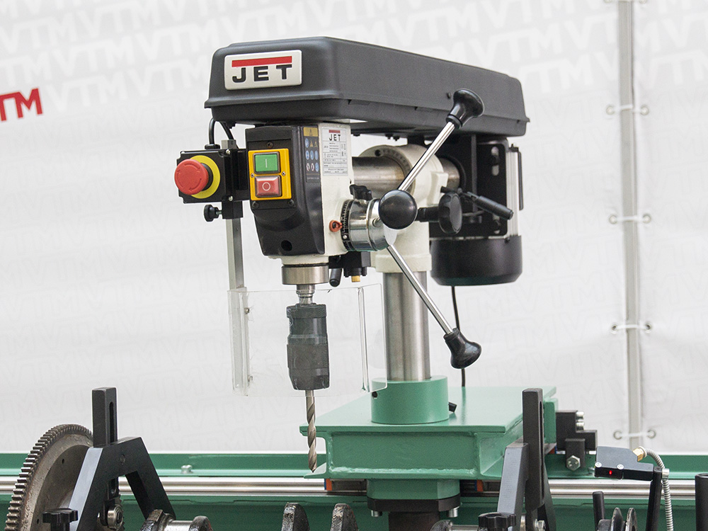
Drilling module
The drilling module, mounted on its own guides, is designed to eliminate rotor unbalance without removing it from the machine. This solution increases productivity by allowing corrections to be made…
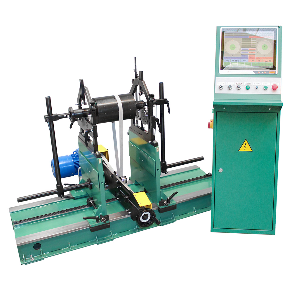
Hard-bearing balancing machine for medium-weight rotors up to 100 kg
Maximal weight, kg
Maximal diameter, mm
Maximum length, mm
The 9D715 is a pre-resonant type machine which has been designed to solve a wide range of problems. The machine has become very popular in many repair shops and services, as well as in production facilities in various industries, as it has the ability to balance parts weighing from 1 to 100 kg. Such a range of load capacity and well thought-out design of all components of the machine made it one of the most versatile machines of this type.
The equipment allows balancing parts of any configuration, thanks to the patented design “MODULAR DESIGN”, which allows changing the characteristics of the machine by replacing modules or accessories, thus the machine can be used for balancing inter-support rotors, parts in their own bearings and using mandrels to balance single plane rotors of the “disk” type, even if they do not have their own journals for installation. In addition, the design of the protective bracket with radial stops allows safe handling of cantilevered parts, eliminating the possibility of their tipping over during balancing.
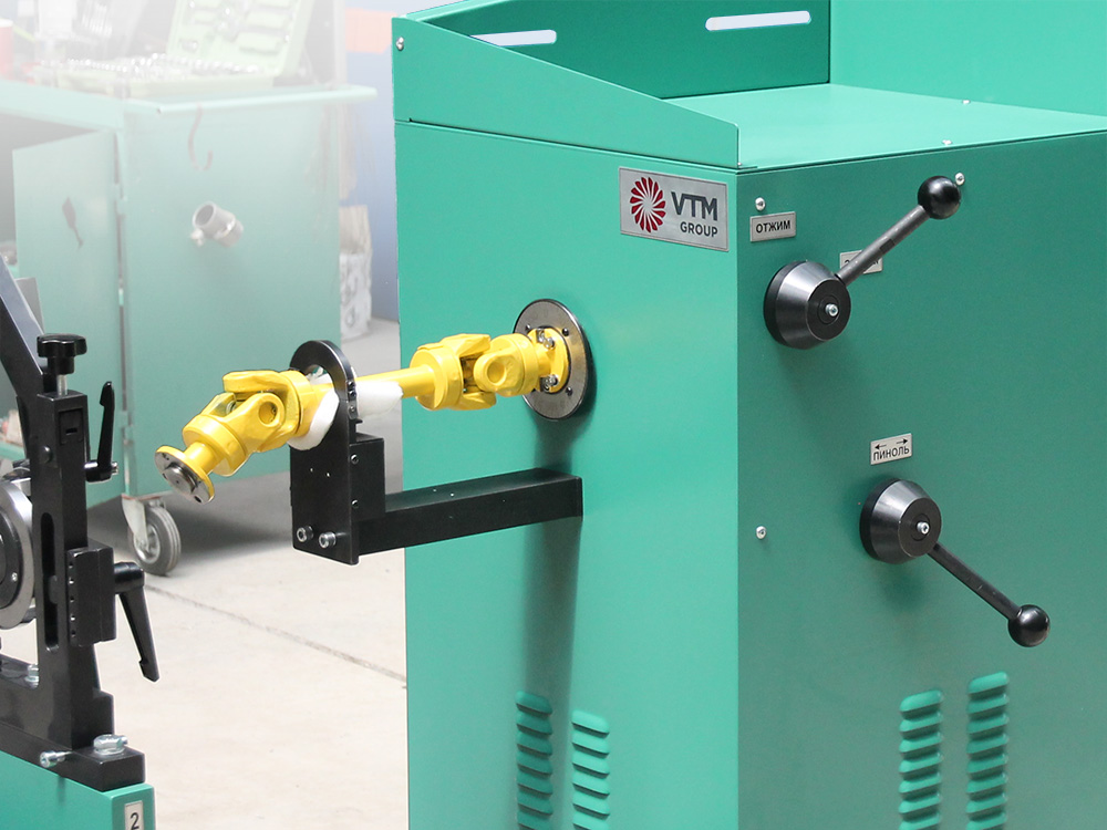
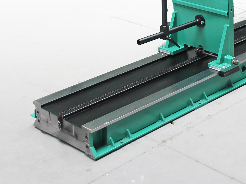
The standard design of the machine contains a monolithic bed, two supports of pre-resonance type that are made of a single piece of sheet metal, as well as “belt drive” having a patented unique design “LONG STROKE” that allows you to work with a large range of products that differ significantly in size using only two types of drive belts instead of 20. Safety of work with “belt drive” is provided by axial stops that limit axial displacement of the part during balancing and adjustment. “Axial” and “radial” stops are also made by patented technology “MOVING ROLLER” that allows to exclude the occurrence of measurement errors associated with the contact of the stops with the workpiece.
The control of the frequency-controlled electric drive as well as the unbalance measurement process and the various machine systems is realized by means of a control panel, which is part of the control cabinet containing modern electrical components ensuring the reliability of the machine systems.
The PAK-1 unbalance measuring unit represents the latest generation of measuring complexes for dynamic balancing, combining high precision, stability, and ease of use. It’s designed to tackle a wide range of rotor balancing tasks, from simple to the most complex, requiring precise measurements.
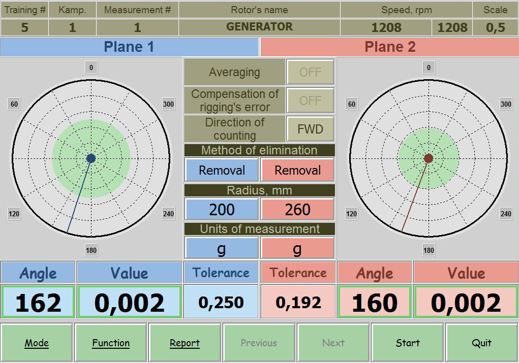
Based on an industrial fanless computer with a touchscreen and a multi-channel measuring unit, the system ensures reliability and a long service life, even under intensive use. The PAK-1 utilizes a universal measuring path and modern component base, allowing for equally high accuracy when working with all types of rotors.
Its intuitive interface, self-calibration capability, and automation of key operations make the complex a convenient tool for both experienced specialists and beginners.
|
Parameter |
Value |
|---|---|
|
Balancing rotors weight range, kg |
1 – 100 |
|
Maximum rotor diameter (over the bed), mm |
1100 |
|
Distance between rotor bearing journal centers, mm, min/max |
150 -1350 |
|
Rotor bearin journals diameter, mm |
20 – 140 |
|
Machine type |
Hard-bearing |
|
Support type |
Rollers |
|
Minimal achievable residual specific unbalance, gmm/kg |
0.4 |
|
Rotor rotation speed range, rpm |
300 – 1500 |
|
Drive type |
Belt |
|
Electric motor power, kW |
2.2 |
|
Power supply parameters |
400V ± 10%, 3 Ph, 50Hz ± 1 |
|
Balancing system |
PAK-1 |
|
Overall machine dimensions (length x width x height), mm |
2100 x 1100 x 1500 |
|
Machine weight, kg |
450 |
Your questions — our technical solutions
The 9D715 is a powerful universal solution for balancing large-sized, medium-weight rotors. Thanks to the increased swing over bed (1100 mm), it is optimal for:
Industrial fan and pump impellers.
Electric motor rotors.
Various drums and conveyor rollers.
Lightweight printing equipment shafts.
Yes, the 9D715 is designed to operate in the mass range from 1 to 100 kg. The reinforced sub-resonant design ensures measurement stability at maximum loads, guaranteeing process safety even with significant initial unbalance.
In the standard version, the maximum distance between support centers is 1350 mm. However, the 9D715 features a modular structure: upon customer request, we can supply an optionally extended bed. This allows for a significant increase in the center-to-center distance for working with long shafts while maintaining the rigidity and accuracy of the measuring system.
The machine ensures a specific residual unbalance of 0.4 g·mm/kg. This guarantees balancing to accuracy classes G1 and G2.5 (according to ISO 21940), which is the standard for the reliable operation of industrial dynamic equipment.
Yes, the machine is set up for a new product type by the operator using trial runs with calibration weights.
This approach offers several key advantages for B2B production:
Maximum Sensitivity: Calibration allows adapting the measuring system to the specific geometry and mass of the rotor, minimizing error.
Accuracy Control: The operator can verify and confirm measurement accuracy at any time, eliminating the accumulation of errors during long-term operation.
Flexibility: The machine maintains reference-level accuracy even with non-standard or complex parts, as the system is tuned to the actual response of the specific rotor.
Leave a request and our manager will contact you to answer questions via your preferred messenger.