


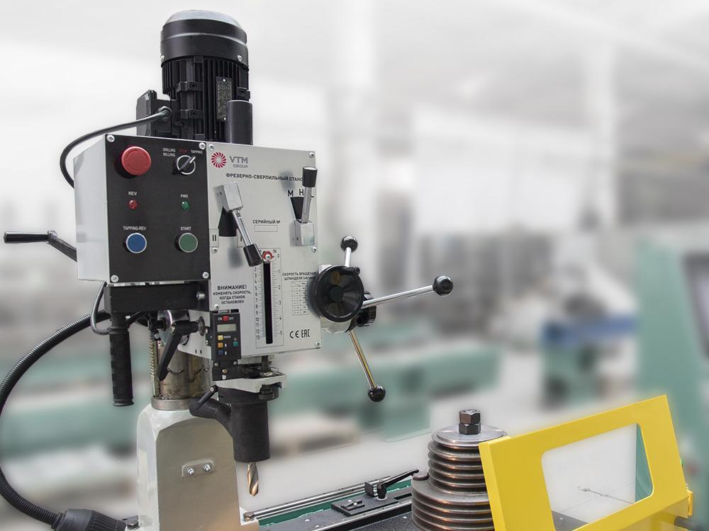
Drilling / milling module
The drilling and milling module, mounted on independent guides, allows precise machining of rotors directly on the balancing machine. This integrated solution increases efficiency by enabling both unbalance correction and…
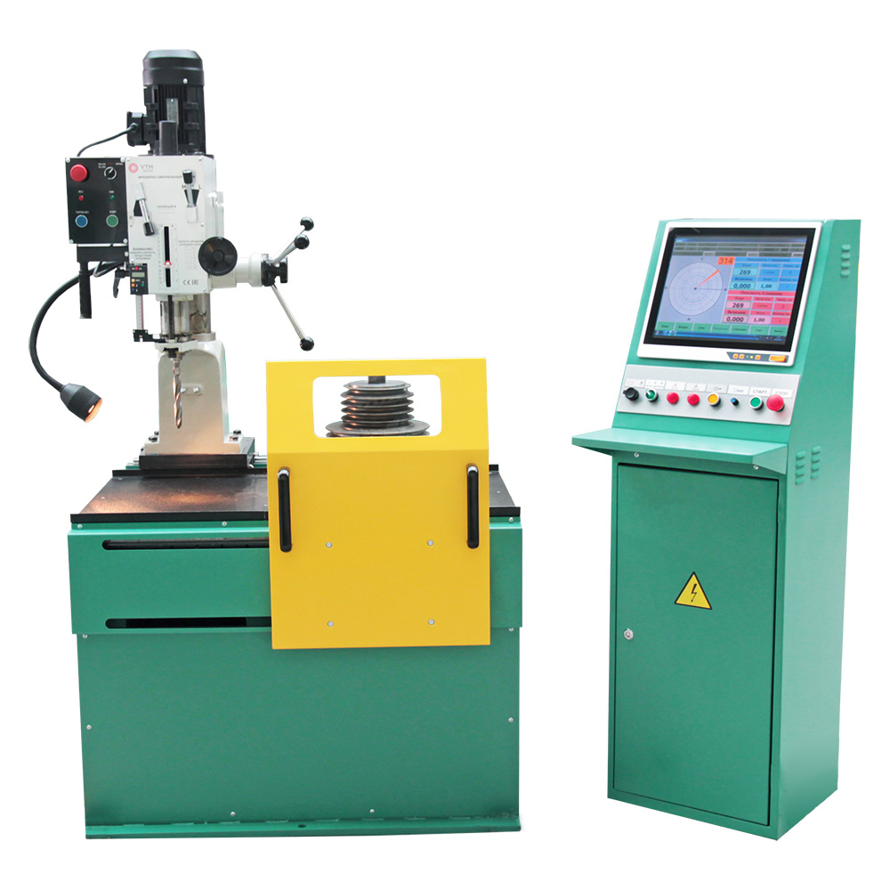
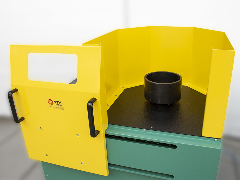
Vertical balancer for medium rotors up to 100kg, robust construction, reliable operation
Maximal weight, kg
Maximal diameter, mm
Maximum height, mm
The balancing machine model 97V100 is a special equipment with a vertical axis of rotation. The machine is designed for balancing single-plane rotors with a weight not exceeding 100 kg. The machine can be used both in repair shops with a large nomenclature of balancing products and at productions with small batch and serial production.
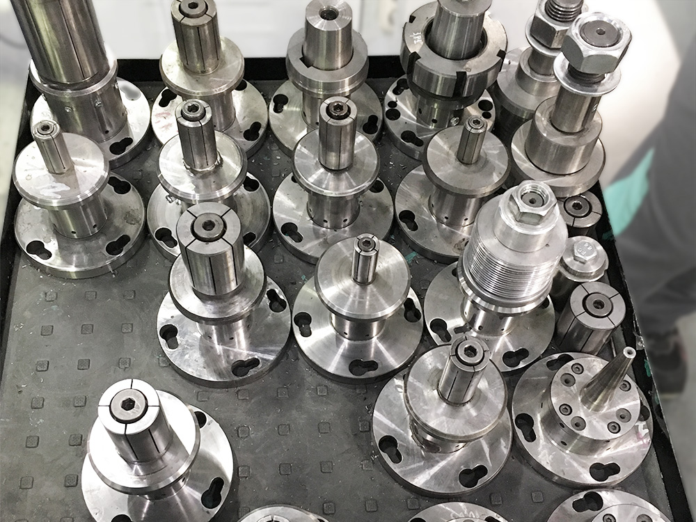
It is possible to balance such parts on the machine:Disk-type component optimization – Design specifically optimized for diverse disk-type rotors including automotive components, industrial discs, and cutting tools. The optimization ensures compatibility with components lacking traditional bearing surfaces.
Automotive component accommodation – Specialized capability for dual mass flywheels, torque converters, clutch baskets, and brake components. The design accommodates challenging automotive geometries while maintaining measurement precision.
Industrial application versatility – Design flexibility enables balancing of pump impellers, fan components, couplings, and separator discs across diverse industrial applications. The versatile configuration maintains accuracy across varied component types.
Custom specification capability – Full production cycle manufacturing enables custom machine configurations differing from standard specifications. This capability accommodates unique application requirements while maintaining design integrity.
Maximum envelope accommodation – Support for rotors up to 550mm diameter and 200mm height within 100kg weight capacity provides substantial component range. The envelope specifications accommodate diverse disk-type industrial and automotive components.
Serial production optimization – Design features optimized for efficient operation in serial, small-scale, and single production environments. The optimization provides operational flexibility across diverse manufacturing scenarios while maintaining consistent performance.
The PAK-1V unbalance measuring unit is a 2-plane measuring balancing system for balancing disc-type rotors on vertical balancing machines. It can perform static (single-plane) balancing in dynamic mode on a two-plane balancing machine.
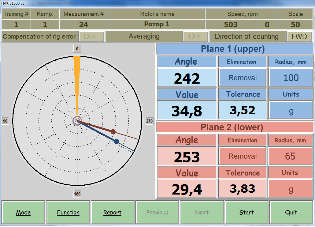
Based on an industrial fanless computer with a touchscreen and a multi-channel measuring unit, the system ensures reliability and a long service life, even under intensive use. The PAK-1V utilizes a universal measuring path and modern component base, allowing for equally high accuracy when working with all types of rotors.
Its intuitive interface, self-calibration capability, and automation of key operations make the complex a convenient tool for both experienced specialists and novice beginners.
|
Parameter |
Value |
|---|---|
|
Balancing rotors weight range, kg |
1 – 100 |
|
Maximum rotor diameter (over the bed), mm |
550 |
|
Maximum rotor height, mm |
200 |
|
Machine type |
Hard-bearing |
|
Minimal achievable residual specific unbalance, gmm/kg |
4 |
|
Rotor rotation speed range, rpm |
300 – 1000 |
|
Number of measured rotor correction planes |
1 & 2 |
|
Electric motor power, kW |
4 |
|
Power supply parameters |
400V ± 10%, 3 Ph, 50Hz ± 1 |
|
Balancing system |
PAK-1V |
|
Overall machine dimensions (length x width x height), mm |
1800 x 1100 x 1500 |
|
Machine weight, kg |
700 |
Leave a request and our manager will contact you to answer questions via your preferred messenger.