


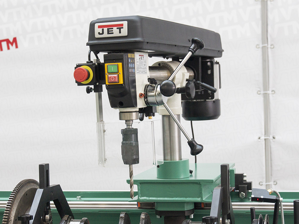
Drilling module
The drilling module, mounted on its own guides, is designed to eliminate rotor unbalance without removing it from the machine. This solution increases productivity by allowing corrections to be made…
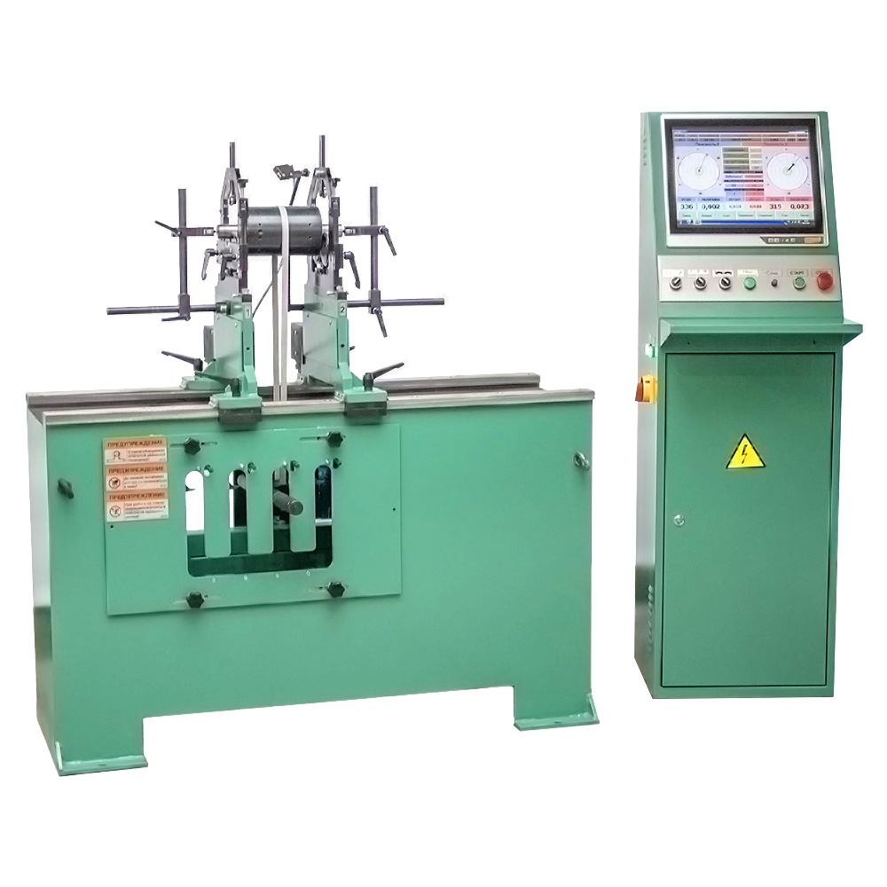
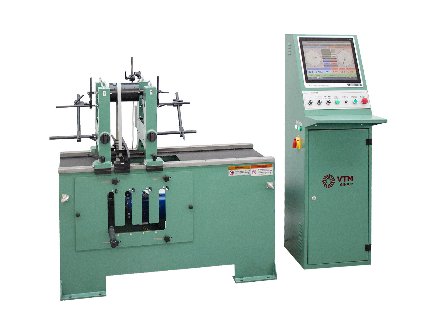
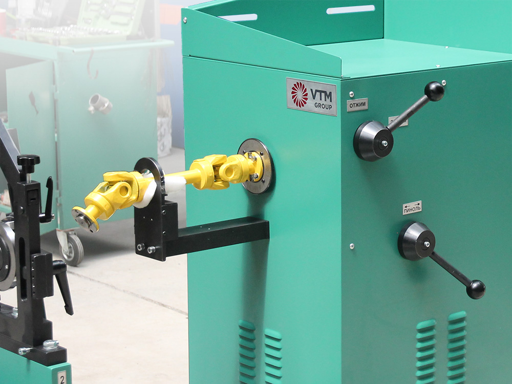
Industrial belt-driven balancer for lightweight rotors up to 60 kg
Maximal weight, kg
Maximal diameter, mm
Maximum length, mm
Lightweight balancing machine 9A714 is used to balance rotors of various designs, the mass of which does not exceed 60 kg. The high sensitivity of the machine allows you to work with unbalances of very small magnitudes.
This series of machines has many innovative technical solutions that make balancing simple and accessible to anyone. The machines have high performance and functionality, which makes them in demand in manufacture in various industries.
All machines of this series have a high accuracy of determining imbalance – 0.4 g ∙ mm / kg, (by special order 0.1 g ∙ mm / kg can be made). This accuracy is a combination of many factors, including the merit of machine design features:
Special features of this machine include very narrow supports (42 mm support width), which allows balancing of complex configuration parts such as crankshafts of cars, ship and railway turbochargers, turbochargers of cogeneration plants, etc. At the same time, these machines can be used for other simpler parts in terms of configuration such as electric motor rotors, all sorts of fans. This machine is also often used for balancing wood-cutting tools during their production.
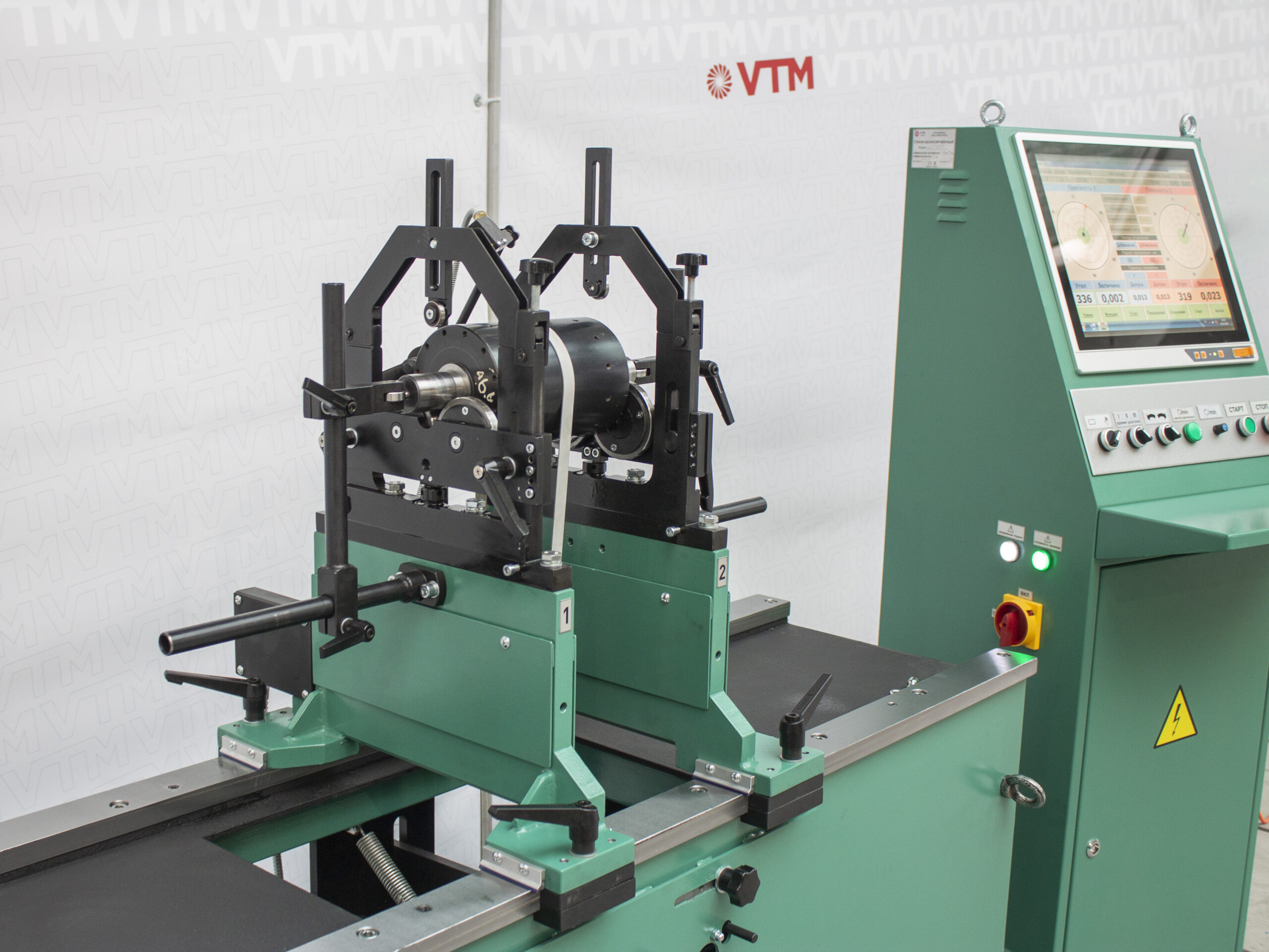
The PAK-1 unbalance measuring unit represents the latest generation of measuring complexes for dynamic balancing, combining high precision, stability, and ease of use. It’s designed to tackle a wide range of rotor balancing tasks, from simple to the most complex, requiring precise measurements.
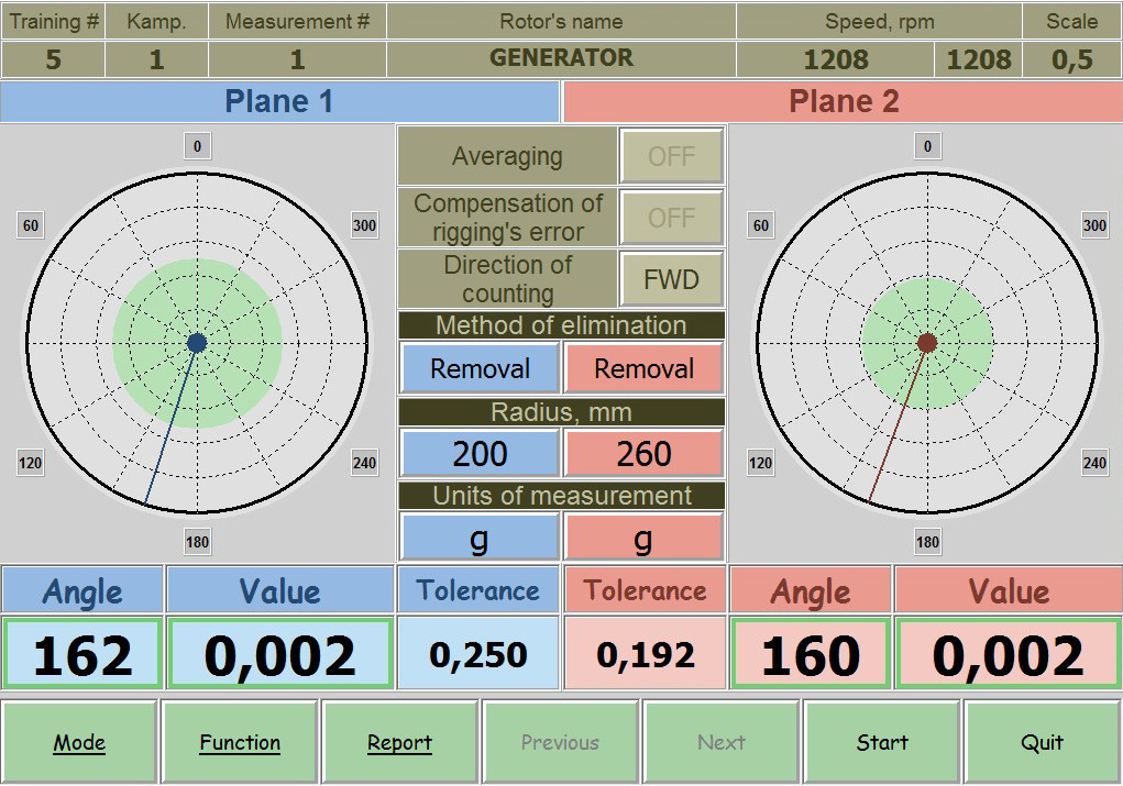
Based on an industrial fanless computer with a touchscreen and a multi-channel measuring unit, the system ensures reliability and a long service life, even under intensive use. The PAK-1 utilizes a universal measuring path and modern component base, allowing for equally high accuracy when working with all types of rotors.
Its intuitive interface, self-calibration capability, and automation of key operations make the complex a convenient tool for both experienced specialists and beginners.
|
Parameter |
Value |
|---|---|
|
Balancing rotors weight range, kg |
0.6 – 60 |
|
Maximum rotor diameter (over the bed), mm |
700 |
|
Distance between rotor bearing journal centers, mm, min/max |
10 – 1100 |
|
Rotor bearin journals diameter, mm |
10 – 50 |
|
Machine type |
Hard-bearing |
|
Support type |
Rollers |
|
Minimal achievable residual specific unbalance, gmm/kg |
0.4 |
|
Rotor rotation speed range, rpm |
200 – 2000 |
|
Drive type |
Belt |
|
Electric motor power, kW |
1.5 |
|
Power supply parameters |
400V ± 10%, 3 Ph, 50Hz ± 1 |
|
Balancing system |
PAK-1 |
|
Overall machine dimensions (length x width x height), mm |
1860 x 1240 x 1450 |
|
Machine weight, kg |
350 |
Your questions — our technical solutions
The 9A714 is a universal horizontal machine designed for the medium-weight rotor segment. Its technical capabilities allow for the balancing of:
Small electric motor rotors.
Centrifugal pump and compressor shafts.
Passenger car crankshafts.
Machine tool spindles.
Fan impellers and smoke exhausters with a diameter of up to 700 mm.
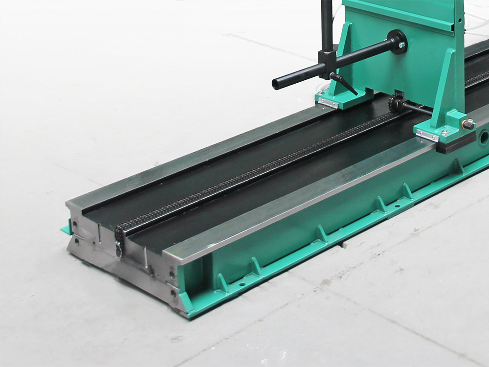
Yes, the 9A714 is specifically designed for parts weighing from 0.6 to 60 kg. A robust bed and reinforced support pedestals provide the necessary structural rigidity, which allows for achieving high balancing accuracy even when operating at the maximum weight limit.
The standard bed length provides a distance between rotor bearing centers of up to 1100 mm. If your rotor has a greater total length, but its bearing surfaces (journals) are located within this range, the machine will handle the task. For significantly longer and larger items, we suggest considering the 9D715 balancing machine with an extended bed.
The 9A714 ensures high balancing accuracy with a minimum achievable specific residual unbalance of 0.4 g·mm/kg. This allows for the successful balancing of parts according to accuracy classes G1 and G2.5 per ISO 21940, which fully covers the needs of most general mechanical engineering and equipment repair sectors.
Yes, the machine is set up for a new product type by the operator using trial runs with calibration weights.
This approach offers several key advantages for B2B production:
Maximum Sensitivity: Calibration allows adapting the measuring system to the specific geometry and mass of the rotor, minimizing error.
Accuracy Control: The operator can verify and confirm measurement accuracy at any time, eliminating the accumulation of errors during long-term operation.
Flexibility: The machine maintains reference-level accuracy even with non-standard or complex parts, as the system is tuned to the actual response of the specific rotor.
Leave a request and our manager will contact you to answer questions via your preferred messenger.